AMWA BCP-008-01: Receiver status monitoring
- Introduction
- Use of Normative Language
- Definitions
- Prerequisites
- Receiver monitoring
![]()
Introduction
Alarms are context and workflow specific, and in general determined by a higher level monitoring system, with different calculations for different users. For example, a hardware error status (such as link down) from a device not actively being used would not cause an alarm to a live workflow operator, but the same status condition would escalate an alarm to a maintenance engineer who needs to prepare that device for future operational use.
This BCP document does not attempt to define alarms but instead it describes the expectations, behavior and conformance requirements for Devices with stream Receivers in terms of status monitoring.
The overall status concepts defined in this document are intended to make it easy to calculate a typical operator alarm condition. In simple systems with no higher level monitoring system, the overallStatus can be used directly as a simple pre-defined non-configurable operator alarm condition, without in any way limiting a monitoring system’s ability to take the same status values and calculate one or more different alarm conditions appropriate to other desired workflows or users.
This document relies on previous familiarity with the following existing documents:
- NMOS Control Framework
- NMOS Control Protocol
- NMOS Discovery and Registration
- NMOS Device Connection Management
The technical models referenced in this document are fully published in the Monitoring NMOS Control Feature Set.
The following domains are covered in terms of status monitoring with specific sections for each:
Use of Normative Language
The key words “MUST”, “MUST NOT”, “REQUIRED”, “SHALL”, “SHALL NOT”, “SHOULD”, “SHOULD NOT”, “RECOMMENDED”, “MAY”, and “OPTIONAL” in this document are to be interpreted as described in RFC-2119.
Definitions
The NMOS terms ‘Controller’, ‘Node’, ‘Source’, ‘Flow’, ‘Sender’, ‘Receiver’ are used as defined in the NMOS Glossary.
Receiver activation - An IS-05 activation which results in the Receiver having the required transport parameters and a master_enable status of true. This can happen for an idle receiver but also when the receiver is already activated and a client is applying new transport parameters.
Prerequisites
Devices in conformance to this BCP MUST comply with NMOS Control Framework for generating device models.
Devices in conformance to this BCP MUST comply with NMOS Control Protocol to expose device models via a standard API with full support for notifications.
Devices in conformance to this BCP MUST comply with NMOS Discovery and Registration to create, describe and register Nodes, Devices and Receiver resources.
Devices in conformance to this BCP MUST comply with NMOS Device Connection Management to perform connection management actions against Receiver resources.
Receiver monitoring
The technical model describing the monitoring requirements for a receiver is NcReceiverMonitor.
This model inherits from the baseline status monitoring model NcStatusMonitor.
Receiver monitors MUST implement NcReceiverMonitor directly or derive a vendor specific variant from NcReceiverMonitor which MAY add more statuses, properties and methods but MUST still comply with the requirements set out in this specification.
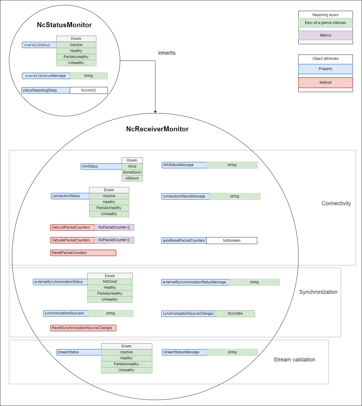 |
|---|
| Receiver monitoring model |
Receiver status reporting delay
The statusReportingDelay property allows clients to customize the reporting delay used by devices to report statuses. Devices MUST use 3s as the default value when the receiver monitor object is first constructed and MUST allow it to be changed to values within the device’s published constraints. Devices MUST allow setting the statusReportingDelay property to a value of 3s. All domain specific statuses are impacted by the configured statusReportingDelay as follows:
-
A receiver is expected to go through a period of instability upon activation. Therefore, on Receiver activation domain specific statuses offering an
Inactiveoption MUST transition immediately to the Healthy state. Furthermore, after activation, as long as the Receiver isn’t being deactivated, it MUST delay the reporting of non Healthy states for the duration specified bystatusReportingDelay, and then transition to any other appropriate state. -
Once any Receiver activation
statusReportingDelayhas elapsed and the Receiver isn’t being deactivated, all domain specific statuses MUST delay the transition to a more healthy state by the configuredstatusReportingDelayvalue and MUST only make the transition if the healthier state is maintained for the duration. All domain specific statuses MUST make a transition to a less healthy state without delay.
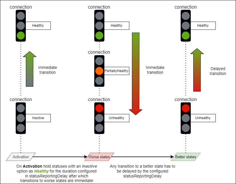 |
|---|
| Status reporting delay example |
Receiver status transition counters
All receiver specific domain statuses have an associated status transition counter property. These increment each time the associated status transitions to a less healthy state. Transitions to/from neutral states like Inactive or NotUsed are ignored.
The intention is that these properties store historical negative trend transitions for each status.
The list of all status transition counter properties is:
- linkStatusTransitionCounter
- connectionStatusTransitionCounter
- externalSynchronizationStatusTransitionCounter
- streamStatusTransitionCounter
Devices MUST be able to reset ALL status transition counter properties in the following two ways:
- When a receiver activation occurs if
autoResetCountersis set totrue - When a client invokes the
ResetCountersmethod
The autoResetCounters property allows clients to configure if ALL counters automatically reset with each Receiver activation (by default devices MUST have this enabled). If this is enabled, receivers MUST reset ALL counters to 0 after each activation. Devices MUST allow setting the autoResetCounters property to a value of true and MAY allow setting the property to false. This supports use cases where users do not want to reset automatically after each activation.
Receiver overall status
The purpose of the overallStatus is to abstract and combine the specific domain statuses of a monitor into a single status which can be more easily observed and displayed by a simple client.
Note: The overallStatus might remain the same even when specific domain statuses change. However, the overallStatusMessage might change to indicate that a different combination of internal states is causing the current overallStatus value.
Devices MUST follow the rules listed below when mapping specific domain statuses in the combined overallStatus:
- When the Receiver is Inactive the overallStatus uses the Inactive option
- When the Receiver is Active the overallStatus takes the least healthy state of all domain statuses (if one status is PartiallyHealthy (or equivalent) and another is Unhealthy (or equivalent) then the overallStatus would be Unhealthy)
- The overallStatus is Healthy only when all domain statuses are either Healthy or a neutral state (e.g. Not used, Inactive)
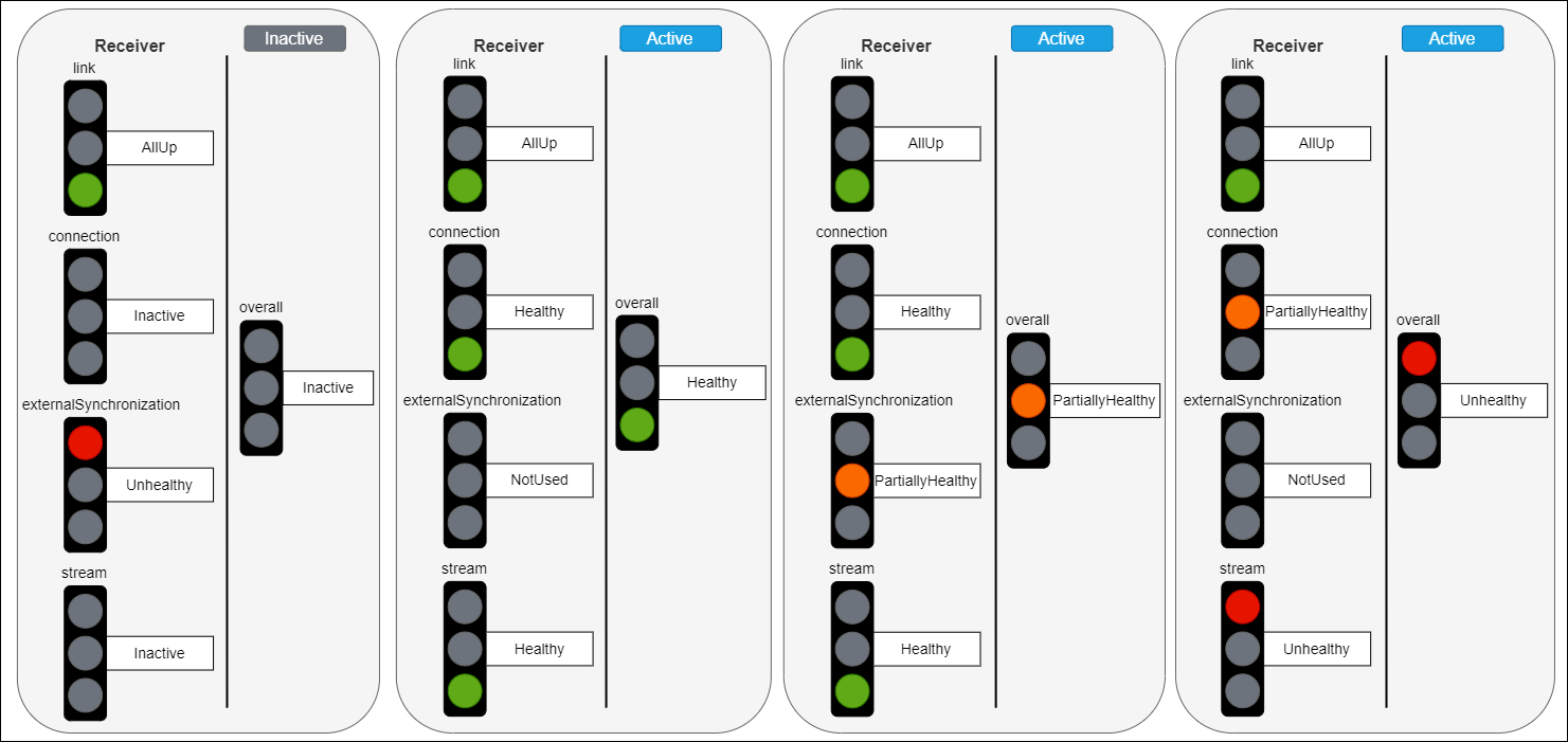 |
|---|
| Overall status mapping examples |
Receiver connectivity
NcReceiverMonitor includes the following specific items covering the connectivity domain:
- Properties
- linkStatus
- linkStatusMessage
- linkStatusTransitionCounter
- connectionStatus
- connectionStatusMessage
- connectionStatusTransitionCounter
- Methods
- GetLostPackets
- GetLatePackets
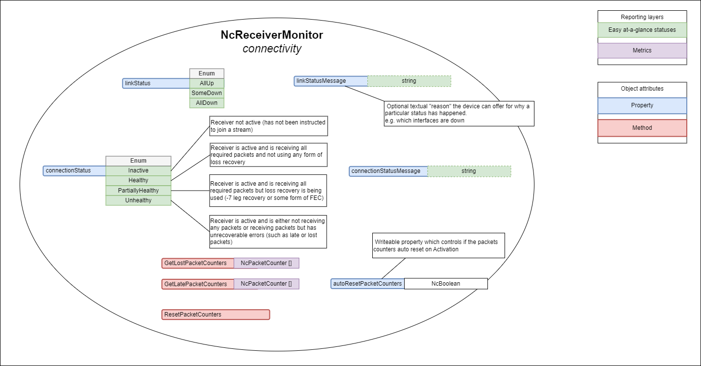 |
|---|
| Receiver connectivity (explanatory notes are informative) |
Link status
The linkStatus property allows devices to expose the health of all the physical links associated with the receiver.
Devices MUST report the linkStatus as follows:
- AllUp when all of the interfaces are Up (equivalent to a Healthy state)
- SomeDown when some of the interfaces are Down (equivalent to a PartiallyHealthy state)
- AllDown when all interfaces are Down (equivalent to an Unhealthy state)
The linkStatusMessage is a nullable property where devices MAY offer the reason and further details as to why the current status value was chosen.
Devices are RECOMMENDED to publish information about which interfaces are down in the linkStatusMessage.
Example:
NIC1, NIC2 are down
Connection status
The connectionStatus property allows devices to expose the health of the receiver with regards to receiving stream packets successfully. Other connection problems like 802.1x authorization, DHCP and other causes are also reflected in the connectionStatus.
Devices MUST report the connectionStatus as follows:
- Inactive when the receiver is Inactive (this is a neutral state)
- Healthy when the receiver is Active and receiving all required packets without using any form of loss recovery
- PartiallyHealthy when the receiver is Active and is receiving all required packets but some form of loss recovery is being used (e.g. redundant leg recovery or some form of FEC)
- Unhealthy when the receiver is Active and is either not receiving any packets or receiving packets but has unrecoverable errors (such as late or lost packets)
The connectionStatusMessage is a nullable property where devices MAY offer the reason and further details as to why the current status value was chosen.
Late and lost packets
The receiver monitoring model provides means of gathering metrics around late and lost stream packets. These are not statuses but instead enable further analysis when link status or connection status indicate problems (are PartiallyHealthy or Unhealthy).
Lost packets are packets that never arrived. Late packets are packets that arrived but arrived too late to be usable by presentation time.
Devices with capabilities to detect late or lost packets MUST implement the following methods:
- GetLostPacketCounters - returns a non empty collection of counters which hold the name, description and numeric value of the counter (this allows more capable devices to report lost packets across different interfaces).
- GetLatePacketCounters - returns a non empty collection of counters which hold the name, description and numeric value of the counter (this allows more capable devices to report late packets across different interfaces).
Devices with capabilities to detect late or lost packets MUST be able to reset ALL lost and late packet counters in the following two ways:
- When a receiver activation occurs if
autoResetCountersis set totrue - When a client invokes the
ResetCountersmethod
For implementations which cannot measure individual late packets the late counters MUST at the very least increment every time the presentation is affected due to late packet arrival.
When devices do not have the capability to detect lost or late packets they MUST:
- Implement the GetLostPacketCounters method but return an empty collection
- Implement the GetLatePacketCounters method but return an empty collection
Receiver synchronization
NcReceiverMonitor includes the following specific items covering the synchronization domain:
- Properties
- externalSynchronizationStatus
- externalSynchronizationStatusMessage
- externalSynchronizationStatusTransitionCounter
- synchronizationSourceId
 |
|---|
| Receiver synchronization (explanatory notes are informative) |
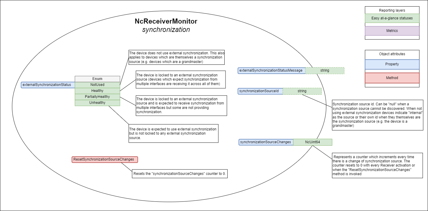
External synchronization status
The externalSynchronizationStatus property allows devices to expose the health of the receiver with regards to its synchronization mechanisms.
Devices MUST report the externalSynchronizationStatus as follows:
- NotUsed when the receiver is not intending to use external synchronization or when the device is itself the synchronization source (this is a neutral state)
- Healthy when the receiver is locked to an external synchronization source (devices which expect synchronization from multiple interfaces are receiving it across all of them)
- PartiallyHealthy when the receiver is locked to an external synchronization source and is expected to receive synchronization from multiple interfaces but some are not providing synchronization (Receivers MUST also temporarily transition to this state when detecting a synchronization source change)
- Unhealthy when the receiver is expected to use external synchronization but is not locked to any external synchronization source
The externalSynchronizationStatusMessage is a nullable property where devices MAY offer the reason and further details as to why the current status value was chosen.
Devices are RECOMMENDED to publish in the externalSynchronizationStatusMessage property information about the previous synchronization source and originating interface as well as the current synchronization source and its originating interface.
Example:
previousSync:baseband from SDI1, currentSync: 0x00:0c:ec:ff:fe:0a:2b:a1 from NIC1
or
previousSync:0x70:35:09:ff:fe:c7:da:00 from NIC1, currentSync: 0x00:0c:ec:ff:fe:0a:2b:a1 from NIC2
Synchronization source change
When devices intend to use external synchronization they MUST publish the synchronization source id currently being used in the synchronizationSourceId property and update the externalSynchronizationStatus property whenever it changes, using null if a synchronization source cannot be discovered. Devices which are not intending to use external synchronization MUST populate this property with internal or their own id if they themselves are the synchronization source (e.g. the device is a grandmaster).
When devices suffer a synchronization source change the externalSynchronizationStatus property MUST temporarily transition to a PartiallyUnhealthy state. It can then return to a different state if the operating conditions match it more closely (returning to a healthier state MUST respect the requirements in the status reporting delay section).
When devices do not use external synchronization they MUST implement the synchronizationSourceId property and set its value to internal.
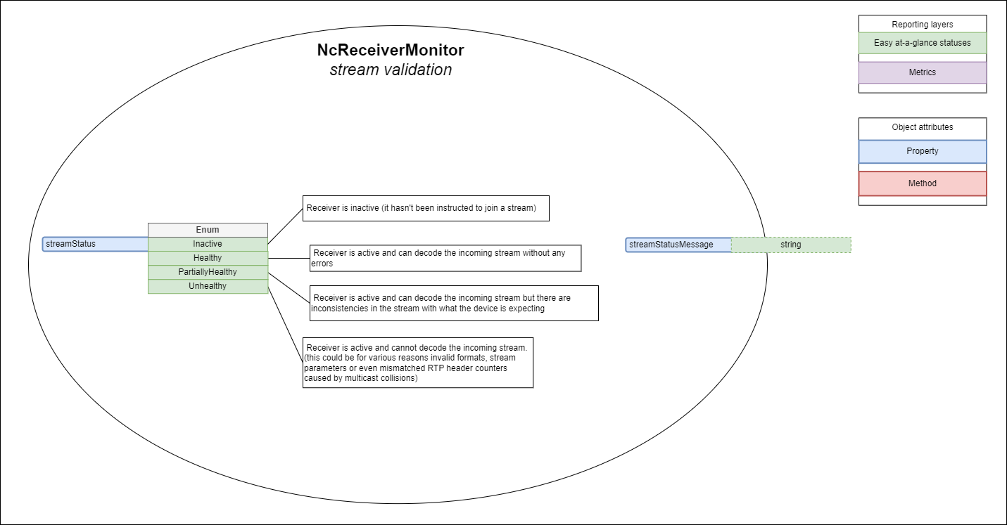
Receiver stream validation
NcReceiverMonitor includes the following specific items covering the stream validation domain:
- Properties
- streamStatus
- streamStatusMessage
- streamStatusTransitionCounter
 |
|---|
| Receiver stream validation (explanatory notes are informative) |
Stream status
The streamStatus property allows devices to expose the health of the receiver with regards to the validity of the stream being received.
Devices MUST report the streamStatus as follows:
- Inactive when the receiver is Inactive (this is a neutral state)
- Healthy when the receiver is Active and can decode the incoming stream without any errors
- PartiallyHealthy when the receiver is Active and can decode the incoming stream but there are inconsistencies in the stream with what the device is expecting
- Unhealthy when the receiver is active and cannot decode the incoming stream
The streamStatusMessage is a nullable property where devices MAY offer the reason and further details as to why the current status value was chosen.
Examples:
Unexpected stream format
Payload ID in RTP stream does not match SDP file
Parameter X does not match expectations
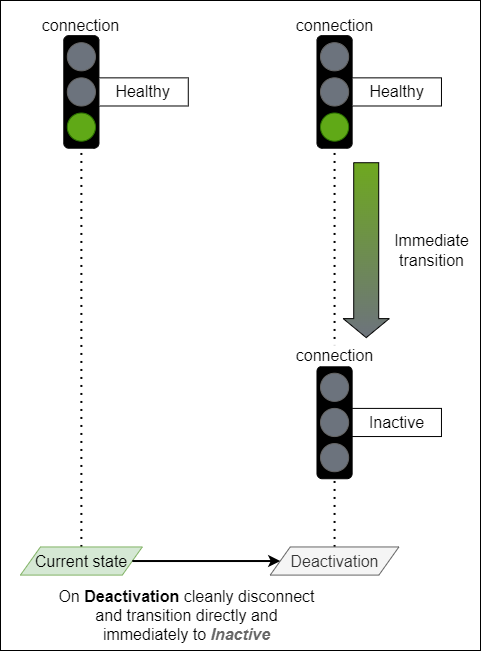
Deactivating a receiver
A Receiver is deactivated after an IS-05 activation results in the Receiver master_enable becoming false.
When a receiver is being deactivated it MUST cleanly disconnect from the current stream by not generating intermediate unhealthy states (PartiallyHealthy or Unhealthy) and instead transition directly and immediately (without being delayed by the statusReportingDelay) to Inactive for the following statuses:
- overallStatus
- connectionStatus
- streamStatus
 |
|---|
| Deactivation transition example |
Touchpoints and IS-04 receivers
Receiver monitors make use of the Touchpoints mechanism inherited from NcObject to attach to the correct receiver identity.
The touchpoints property of any NcReceiverMonitor MUST have one or more touchpoints of which one and only one entry MUST be of type NcTouchpointNmos where the resourceType field MUST be set to “receiver” and the id field MUST be set to the associated IS-04 receiver UUID.
Receiver monitors MUST maintain a 1 to 1 relationship between its role and the receiver resource it monitors (expressed via the touchpoints property) for the lifetime of the IS-04 receiver resource.
Touchpoints example:
[
  {
    "contextNamespace": "x-nmos",
    "resource": {
      "resourceType": "receiver",
      "id": "82fdc03f-76c7-4989-9d05-3ea2cc98875e"
    }
  }
]
NcWorker inheritance
NcStatusMonitor inherits from the NcWorker model.
Since NcReceiverMonitor inherits from the NcStatusMonitor model then it also indirectly inherits from the NcWorker model.
Receiver monitors MUST always have the enabled property set to true.
Receiver monitors MUST NOT allow changes to the enabled property and instead MUST return InvalidRequest to Set method invocations for this property.